Resilmount A237CR
The Resilmount A237CR is a ceiling-only isolation clip used at the intersection of cold-rolled channel (CRC) and furring channel. It wraps and locks over a 1½ × ½-inch, 16-gauge (54-mil) CRC primary channel and resiliently supports the lower furring channel, acoustically decoupling the gypsum ceiling from the suspension system above. Install one A237CR at each designed crossing of the CRC and furring channels.
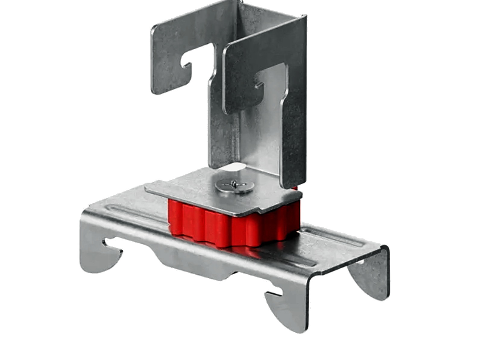
- CRC means cold-rolled channel: The A237CR joins a cold-rolled primary channel to the lower furring channel. It is not a concrete anchor clip, not a reinforced A237R, and it never attaches directly to a slab, deck, bar joist or masonry anchor.
- Installed at the channel crossings: Approved overhead structure or anchor → minimum 12 ga hanger wire (M47 right-angle bracket where an appropriate hanger bracket is needed) → 1-1/2 x 1/2 in, 16 ga (54 mil) CRC → A237CR → 7/8 in or 1-1/2 in compatible furring channel → gypsum board.
- Slides, then locks in two stages: The clip can slide along the CRC while the grid is being aligned. A single rotation locks it over the cold-rolled channel, and a separate two-step engagement locks the lower furring channel into the resilient connection.
- 37 lb acoustical design load: Resilmount lists a 37 lb acoustical design load per clip, plus a separate ceiling tension capacity that depends on the channel gauge and the safety factor used. The most restrictive applicable limit governs.
- Counted from the grid, not the square footage: Total clips = CRC runs x furring runs. A 24 x 48 in interior grid is roughly 1 clip per 8 sq ft and 16 x 48 in roughly 1 per 5.33 sq ft, but those are sanity checks only — the count comes from the reflected ceiling layout after the 6 in perimeter offsets.
Online orders up to 4,999 pieces. For anything larger, call (415) 864-4440 and we'll price the project with you.
A237CR Specifications
- Use on ceilings
- Yes
- Use on walls
- No
- Type
- Intersection clip decoupling the lower furring channel from the upper cold-rolled channel (CRC)
- Upper connection
- Wraps and rotates to lock over 1-1/2 x 1/2 in, 16 ga (54 mil) cold-rolled channel
- Lower connection
- Two-step lock receiving minimum 25 ga hemmed-edge furring channel, 7/8 in or 1-1/2 in depth (compatible published 20 ga options also exist)
- Acoustical design load
- 37 lb per clip
- Ceiling tension capacity — 25 ga channel
- 45 lb at a 2:1 safety factor · 36 lb at 2.5:1
- Ceiling tension capacity — 20 ga channel
- 60 lb at a 2:1 safety factor · 48 lb at 2.5:1
- Standard layout
- Maximum 24 x 48 in o.c.; the installation guide also illustrates 16 x 48 in o.c.
- Perimeter
- Perimeter clips 6 in from the wall
- Hanger wire (separate takeoff)
- Minimum 12 ga wire, no more than 48 in o.c. along each CRC run, hung plumb with alternating double-saddle tie direction
- Width
- 1-3/8 in
- Height including rubber
- 1-1/16 in
- Length
- 3-3/16 in
- Metal thickness
- 0.047 in (18 ga)
- Isolator
- Thermoplastic rubber
- Furring channel splices
- Overlap at least 6 in between clips, fastened with two 7/16 in framing screws or 18 ga tie wire
Making the connection
- 1 — Structure
- Approved overhead structure with anchors by others, verified for pull-out, shear and the actual load at each hanger point
- 2 — Hanger wire
- Minimum 12 ga hanger wire, no more than 48 in o.c. along each CRC run and hung plumb; use an M47 right-angle bracket where an appropriate hanger bracket is needed
- 3 — Cold-rolled channel (CRC)
- 1-1/2 x 1/2 in, 16 ga (54 mil) primary channel, tied with a double saddle tie and alternating the tie direction to control CRC rollover
- 4 — A237CR clip
- Wrapped over the CRC and rotated to lock; it can slide along the channel for alignment before it is locked and the furring is engaged
- 5 — Furring channel
- Minimum 25 ga hemmed-edge furring channel, 7/8 in or 1-1/2 in depth, locked into the resilient lower connection in two steps; splices overlap at least 6 in between clips
- 6 — Gypsum board
- Gypsum board on the furring channel, kept clear of the surrounding construction with the required perimeter gap sealed with resilient non-hardening acoustical sealant
A237CR Preliminary Ceiling Estimate
Built for ceilings. One clip goes at every designed crossing of a cold-rolled channel (CRC) primary run and a lower furring channel, so the count is CRC runs multiplied by furring runs. Resilmount's maximum standard layout is 24 x 48 in o.c., and the installation guide also illustrates a closer 16 x 48 in layout. Perimeter clips sit 6 in from the wall.
The A237CR count covers the CRC-to-furring crossings only. The minimum 12 ga hanger wires that suspend the CRC are counted separately: no more than 48 in o.c. along each CRC run, hung plumb, tied with a double saddle tie and alternating the tie direction to control CRC rollover. Use an M47 right-angle bracket where an appropriate hanger bracket is needed.
Total clips = CRC runs x furring-channel runs, because one clip is required at each designed crossing. As a rough sanity check only, a 24 x 48 in interior grid is about 1 clip per 8 sq ft and a 16 x 48 in grid about 1 per 5.33 sq ft. Those ratios are not a takeoff: the final count is the actual rows and intersections after the 6 in perimeter offsets and the real layout. No cuts or rework allowance is added to a clip count.
The area shortcut at 24 x 48 in on 320 sq ft is 40 clips, which is not the answer. With 6 in perimeter offsets and maximum spacing of 24 in in one axis and 48 in in the other, the plotted grid works out to roughly 54–55 intersections (about 6 x 9, or 5 x 11 depending on run orientation and rounding). Treat this as a planning example only and count the actual reflected ceiling grid.
Preliminary material takeoff only. The A237CR product spec states a maximum of 48 in between clips, while the installation guide specifies the 24 x 48 in standard ceiling layout and shows 16 x 48 in as the closer alternative — this estimator follows the installation layout. Verify the reflected ceiling plan, the CRC and hanger-wire design, the supported loads and the applicable fire-rated design with Resilmount and the engineer of record.
How A237CR compares
| Model | Use | Upper connection | Lower connection | Standard layout |
|---|---|---|---|---|
| A237CRthis | Ceilings only | Locks over 1-1/2 x 1/2 in, 16 ga cold-rolled channel | 7/8 in or 1-1/2 in furring channel in a resilient two-step lock | Max 24 x 48 in o.c. (16 x 48 in shown as the closer option) |
| A237R | Walls and ceilings per its own listing | Fastened directly to the framing member | Furring channel in the clip's resilient connection | Per the A237R installation instructions |