Resilmount A237BR
The Resilmount A237BR is a ceiling-only resilient isolation assembly for dropped gypsum ceilings below steel open-web bar joists. A 1/4-20 bolt passes through the parallel components of the joist chord and is clamped with two fender washers and a Nyloc hex nut, so the integral A237R resilient mount hangs just below the chord and carries the furring channel that runs perpendicular to the joists. It is not intended for wall assemblies.
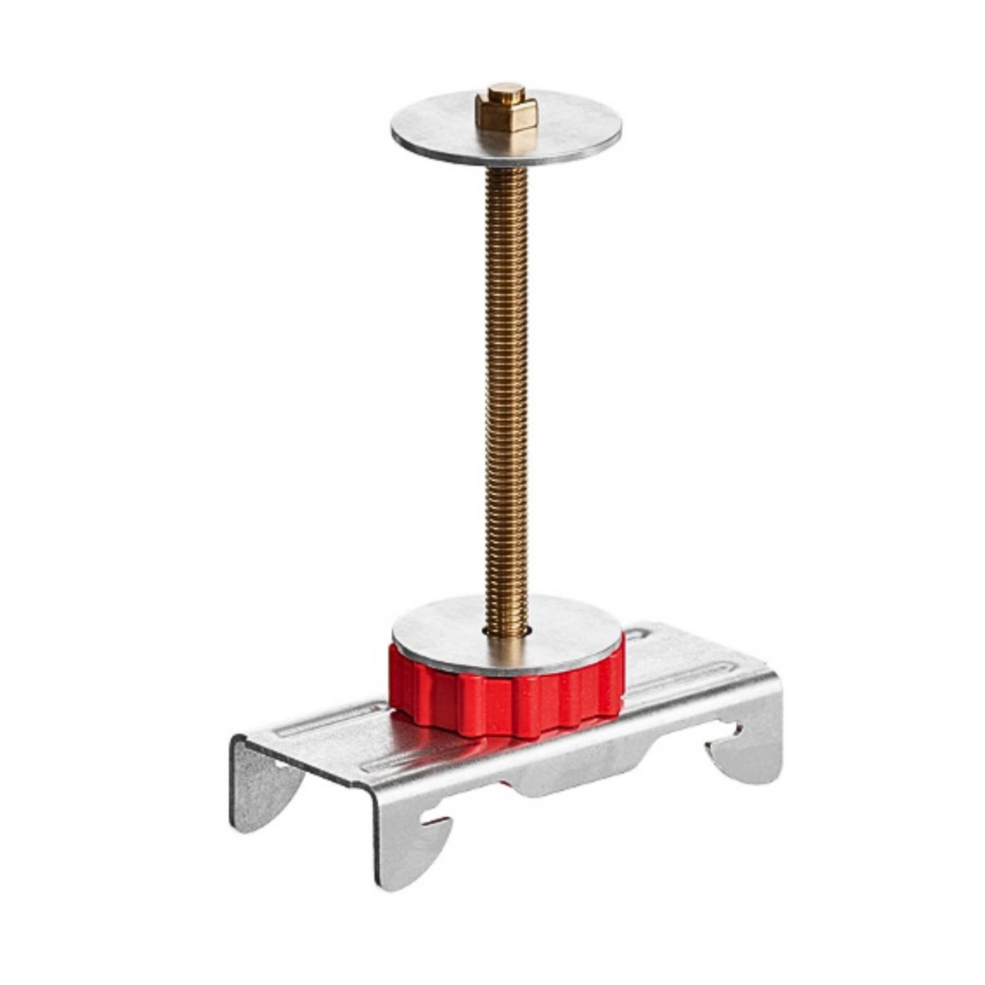
- Bolted through the joist chord: A 1/4-20 bolt passes through the parallel components of the bar-joist chord, with a 1-1/2 x 1/4 in fender washer on each side and a Nyloc hex nut. There is no self-drilling screw, threaded rod or hanger wire in this connection.
- Integral A237R resilient mount: The A237R thermoplastic-rubber mount sits below the chord and receives the furring channel, decoupling the gypsum ceiling from the steel structure above.
- Bolt length matches the chord: A237BR-3, -4 and -5 carry 3, 4 and 5 in bolts for chords of approximately 1, 2 and 3 in. Take the length from measured, approved joist geometry — bolting through a chord needs the joist manufacturer's and engineer's approval.
- 37 lb acoustical design load: Resilmount lists 37 lb per A237BR. Check the full tributary ceiling dead load at every support point and support heavy unrelated loads independently.
- Counted from the support grid: Furring channels run perpendicular to the joists. One A237BR goes at every designed support location, never more than 48 in o.c. along a run, and only where an appropriate bar-joist chord exists.
Online orders up to 4,999 pieces. For anything larger, call (415) 864-4440 and we'll price the project with you.
A237BR Specifications
- Use on ceilings
- Yes — dropped gypsum ceilings below steel open-web bar joists
- Use on walls
- No — not intended for wall assemblies
- Upper connection
- 1/4-20 bolt through the parallel components of the bar-joist chord, two 1-1/2 x 1/4 in fender washers and a 1/4-20 Nyloc hex nut
- Fire-rated applications
- A300 1/4 x 1-1/2 in washer must be installed; without it the clip has no fire rating
- Isolation
- Integral A237R thermoplastic-rubber resilient mount below the chord
- Lower connection
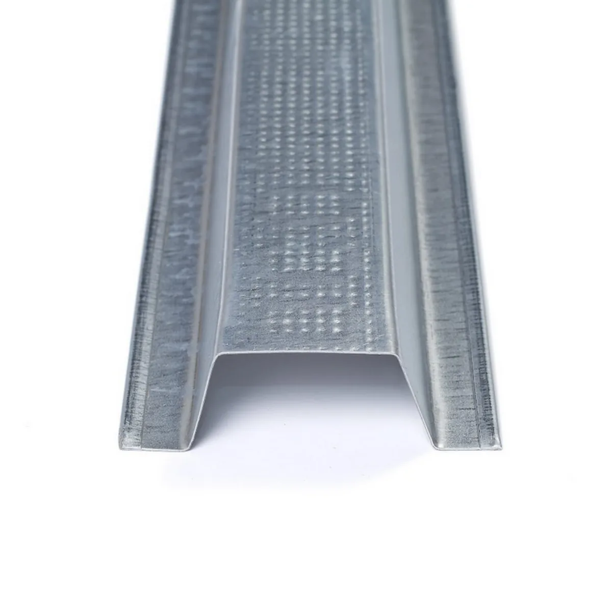
- Compatible 7/8 in or 1-1/2 in furring channel, minimum 25 ga hemmed edge (listed 20 ga variants also exist)
- Channel profile limits
- Top face max 1-1/4 in; flange-to-flange min 2-1/2 in and max 2-3/4 in
- Channel direction
- Furring channels run perpendicular to the bar joists
- Acoustical design load
- 37 lb per A237BR
- Maximum spacing
- 48 in o.c. between A237BR support points along a furring run
- Bolt selection
- A237BR-3 = 3 in bolt (~1 in chord) · A237BR-4 = 4 in bolt (~2 in chord) · A237BR-5 = 5 in bolt (~3 in chord)
- Width
- 1-3/8 in
- Length
- 3-3/16 in
- Overall height including rubber
- 3-3/16 in (BR-3) · 4-3/16 in (BR-4) · 5-3/16 in (BR-5)
- Furring channel splices
- Splice between clips: overlap 6 in and secure with two 7/16 in framing screws or 18 ga tie wire
- Perimeter
- Leave a 1/8–1/4 in gypsum perimeter gap and fill it with acoustical caulk
Making the connection
- 1 — Structure
- Steel open-web bar joist. Not every joist may be drilled or altered — the joist manufacturer and the project engineer must approve the connection
- 2 — Bolt assembly
- 1/4-20 bolt sized for the chord depth (3, 4 or 5 in), two 1-1/2 x 1/4 in fender washers and a 1/4-20 Nyloc hex nut; add the A300 1/4 x 1-1/2 in fire washer where required
- 3 — Resilient mount
- Integral A237R thermoplastic-rubber mount below the chord
- 4 — Furring channel
- Compatible 7/8 in or 1-1/2 in furring channel, minimum 25 ga hemmed edge, installed perpendicular to the bar joists
- 5 — Gypsum ceiling
- Gypsum board on the furring channel with a 1/8–1/4 in perimeter gap filled with acoustical caulk
A237BR preliminary ceiling estimate
The A237BR is used on ceilings under steel bar joists and is not intended for wall assemblies. One A237BR goes at every designed support point: draw the furring runs perpendicular to the actual joists, decide which joist lines support each run, and count those locations. Spacing along a furring run must not exceed 48 in o.c., and a clip can only be placed where an appropriate bar-joist chord exists.
A237BR-4 uses a 4 in 1/4-20 bolt for an approximately 2 in joist chord, with an overall height of 4-3/16 in including the rubber. Take the length from the measured, approved joist-chord geometry and have the project engineer and the joist manufacturer confirm it. Not every open-web joist may be drilled or altered — bolting through a chord requires structural approval. Confirm bolt length with our sales team when ordering.
Identify each furring-channel run and the bar-joist lines chosen to support it, then place one A237BR at every designed support location. The final quantity is the sum of those locations across all furring runs, taken from the reflected ceiling and framing plans. An area factor is only a check when the approved grid is already known — 24 in furring on a 48 in support grid is about one per 8 sq ft. No cuts-and-rework allowance is added to a clip count.
With approved 24 in furring spacing and support lines at no more than 48 in, the area shortcut is 320 / 8 = 40 as a rough interior check only. The order count comes from drawing the furring runs perpendicular to the actual joists and counting every specified A237BR location — edge conditions and the real joist spacing change the number.
Preliminary material takeoff only. Bolting through a bar-joist chord requires the joist manufacturer's and the project engineer's approval, and where a fire-rated assembly is required the A300 1/4 x 1-1/2 in fire washer must be installed. Verify the reflected ceiling plan, the framing plan and the load at every support point before ordering.
How A237BR compares
| Model | Use | Upper connection | Lower connection | Spacing |
|---|---|---|---|---|
| A237BRthis | Ceilings only, below steel open-web bar joists | 1/4-20 bolt through the joist chord with fender washers and a Nyloc nut | 7/8 in or 1-1/2 in furring channel, perpendicular to the joists | Designed support grid, max 48 in o.c. |
| A237R | Per its own listing | Fastened directly to the framing member | Furring channel in the clip's resilient connection | Per the A237R installation instructions |
| A237CR | Ceilings only, on suspended cold-rolled-channel primaries | Locks over 1-1/2 x 1/2 in, 16 ga cold-rolled channel | Furring channel in a resilient two-step lock | One clip per CRC / furring crossing |