PAC International RC-1 BOOST
The PAC International RC-1 BOOST is a small isolator that sits between approved RC-1 resilient channel and the framing at each channel fastening point. There are three parts to the connection: the wood or steel framing, the PAC-supplied screw driven through the RC-1 BOOST and the RC-1 channel flange into that framing, and the RC-1 channel itself, which still carries the gypsum board. Because the screw connection is where a resilient channel most often short-circuits, isolating it is what the BOOST is for. It is installed while the channel is being put up in a new wall or ceiling assembly — it is not normally retrofitted behind finished drywall.
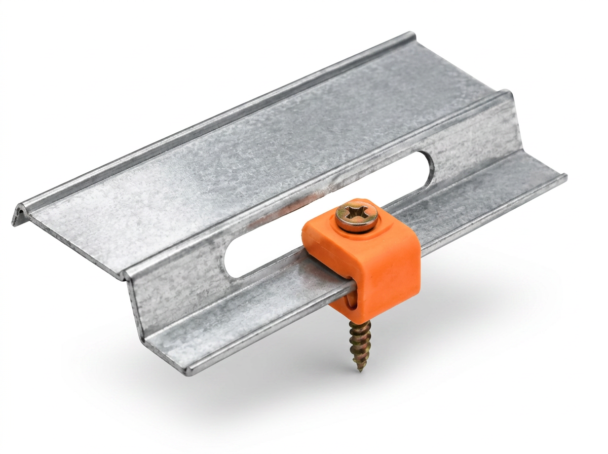
- What it solves: RC-1 channel fastened straight to framing can short-circuit at the screw. The BOOST puts a resilient isolator around that attachment, so the channel-to-framing fastener is no longer a rigid path.
- What it connects: Approved single-leg RC-1 resilient channel to wood or steel framing, using only the PAC-supplied RC-1 BOOST screw. No substitute screws, and never nails.
- Layout and load: Maximum grid 24 in x 16 in on center and a maximum acoustical design load of 13.3 lb per isolator (pull and shear). Supports up to two layers of 5/8 in gypsum board at that maximum grid, subject to the applicable assembly or UL design.
- Installation control: The BOOST goes over the channel's fastening location on the flange, clear of the elongated slots. Tighten only until the screw head just touches the isolator — no overtightening, no visible deformation of the rubber. All RC-1 channels face the same direction.
Online orders up to 4,999 pieces. For anything larger, call (415) 864-4440 and we'll price the project with you.
Volume pricing
$0.85 per clip. Order 250+ clips and pay $0.80 per clip — an extra $0.05 off per clip for each additional 250 clips, down to a $0.50 per clip floor.
Discounts apply automatically in the cart and count boxes and cases toward the total.
RC-1 BOOST Specifications
- Used with
- Approved single-leg RC-1 resilient channel
- Framing
- Wood or steel, new wall and ceiling assemblies
- Max acoustical design load
- 13.3 lb per isolator (pull and shear)
- Maximum grid
- 24 in x 16 in on center
- Gypsum supported
- Up to two layers of 5/8 in at the maximum grid, subject to the approved design
- Cavity created
- 3/4 in between framing face and back of gypsum
- Dimensions
- 1/2 in tall x 5/8 in wide x 3/4 in deep
- Fastener
- PAC-supplied RC-1 BOOST screw only — no substitutions, no nails
- Isolation element
- Rubber-like resilient isolator
- Service conditions
- Interior walls and ceilings, 40–100°F
- Fire-rated work
- Listed designs under UL File R16638; the selected design governs spacing and components
- Not for
- Heavy loads such as cabinets or bookshelves
Installed detail
- Where it goes
- Over the channel's fastening location on the flange, clear of the elongated slots
- Attachment
- PAC-supplied RC-1 BOOST screw only — never nails
- Tightening
- Only until the screw head just touches the isolator — no visible deformation of the rubber
- Channel direction
- All RC-1 channels face the same direction
- Assemblies
- Wood or steel new wall and ceiling assemblies
RC-1 Boost Preliminary Estimate
One RC-1 Boost goes at every designed RC-1-channel-to-framing intersection, so the count is a grid: channel rows multiplied by the framing lines each row crosses. The maximum grid is 24" x 16" on center — with framing at 16" o.c. the channel rows run at 24" o.c., and with framing at 24" o.c. the rows run at 16" o.c.
Butt joints are added manually because the number depends on the channel lengths you are supplied and how the rows are laid out. PAC calls for one RC-1 Boost at each channel end, so each butt joint where two channel ends meet adds two Boosts.
Walls: the first channel/Boost row sits within 3 in of the floor and the top row within 6 in of the ceiling. Gypsum goes up bottom-up on temporary 1/4 in minimum floor shims with a 1/4 in minimum perimeter gap; the shims come out only after every layer is fully fastened to all channels, then the perimeter is acoustically sealed.
The quantity is the number of framing lines crossed by all the RC-1 channel rows — the channel/framing intersections. At the maximum 24" x 16" grid one Boost serves no more than 384 square inches (2.67 sq ft), so about 0.375 Boost per sq ft is a rough early budget only. The final count comes from the actual row and intersection layout.
Rows run at 24" o.c. between 3 in off the floor and within 6 in of the ceiling, giving 6 rows; each row crosses 10 stud lines across 12 ft, so the preliminary count is 60 Boosts and 60 supplied screws. Assumes continuous channel with no butt joints and studs starting at the wall end.
Preliminary material takeoff only. Verify actual framing layout, edge conditions, butt joints, supported loads, the RC-1 channel manufacturer's instructions, PAC's RC-1 Boost instructions and the applicable UL design. In a fire-rated assembly the selected UL design under File R16638 determines final spacing and components — do not add or move isolators to suit a calculator result.
How RC-1 BOOST compares
| Model | Primary Use | Compatible Channel | Fastener | Design Load |
|---|---|---|---|---|
| RC-1 BOOSTthis | Fitting used with approved single-leg RC-1 resilient channel — a low-cost improvement to the channel fastener interface | Approved RC-1 resilient channel | PAC-supplied RC-1 BOOST screw only | 13.3 lb per isolator (max) |
| RSIC-1 | Purpose-built resilient isolation clip that accepts approved hat/furring channel — a different system, not interchangeable with RC-1 BOOST | Approved 7/8 in hat/furring channel | Framing screw per PAC's RSIC-1 instructions | Per PAC's RSIC-1 documentation |
| RC-1 channel alone | Resilient channel fastened directly to framing — more installation-sensitive at the screw connection | n/a — is the channel | Per the channel manufacturer's instructions | Per the channel manufacturer's documentation |