PAC International RSIC-2
The PAC International RSIC-2 is an RSIC-1-family resilient sound isolation clip with a 3/8 in spacer, giving an overall clip-and-channel build-out of about 2 in. PAC describes it as "RSIC-1 with 3/8 in spacer" and publishes the same 36 lb acoustical design load, so it is selected for dimensional coordination rather than for higher capacity: adding its 2 in of build-out to nominal 2x4 framing puts the framing-plus-clip/channel plane at roughly 5-1/2 in, the same depth as nominal 2x6 framing, which can allow standard off-the-shelf 2x6-depth door frames and window casings instead of custom jamb components.
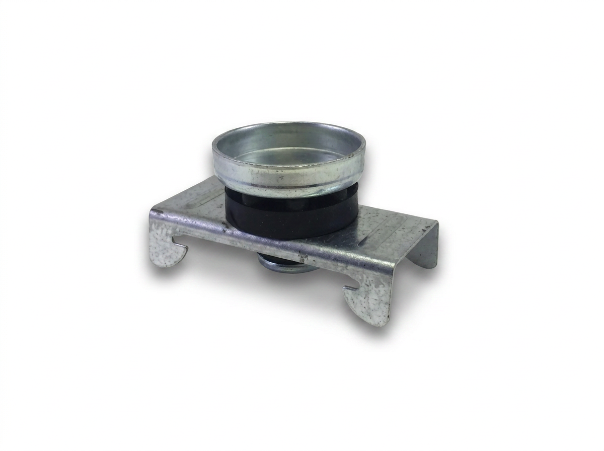
- The 3/8 in spacer is the point: The spacer sets an overall clip and channel build-out of about 2 in. That depth — not load, not spacing — is the reason a project specifies an RSIC-2.
- 2x4 framing that reads as 2x6 depth: Nominal 2x4 framing (3-1/2 in) plus the 2 in build-out is about 5-1/2 in of framing and clip/channel plane, matching nominal 2x6 depth for standard door frames and window casings.
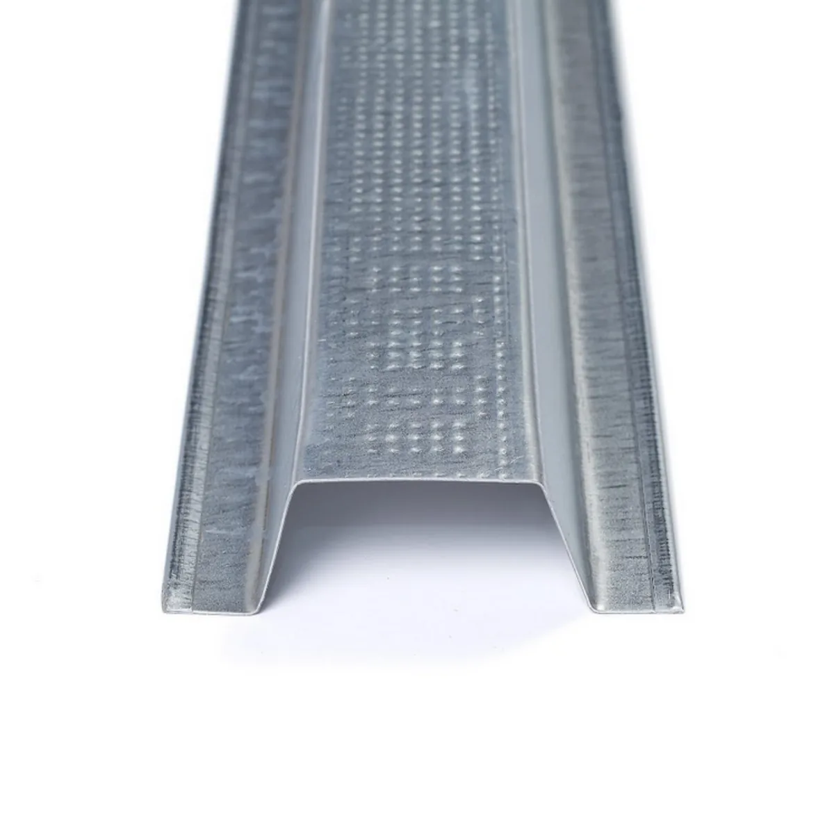
- Standard 7/8 in furring channel: The hook legs receive approved 7/8 in, 25 ga hemmed-edge drywall furring channel. Gypsum fastens only to that channel — never back to the framing.
- Walls and ceilings, on exposed framing: It fastens to wood, steel or approved structure through the rubber isolator and raised spacer cup. For fastening through an existing finished surface, the separate RSIC-2 Retro is the correct product.
- Same layout as the RSIC-1 family: Channel rows and clip spacing follow the approved RSIC-1-family grid. The model number is not permission to open the spacing up.
Price not confirmed
We couldn’t confirm the current price. No payment was taken. Please retry or call us at (415) 864-4440.
RSIC-2 Specifications
- Type
- RSIC-1-family resilient furring-channel clip with a 3/8 in spacer
- Why it is selected
- Dimensional coordination — the ~2 in build-out, not higher load or wider spacing
- Use on walls
- Yes
- Use on ceilings
- Yes
- New construction / retrofit
- New work on exposed framing — see RSIC-2 Retro for existing finished surfaces
- Mounts to
- Wood framing, steel framing or approved structure, through the central ferrule/spacer and rubber isolator
- Channel received
- Approved 7/8 in depth, 25 ga hemmed-edge drywall furring channel
- Acoustical design load
- 36 lb per isolator — the same as the RSIC-1
- Overall build-out
- About 2 in of clip and channel depth from the framing face
- Clip dimension
- About 3 in across the channel hook legs (per PAC's drawing)
- Component dimension
- 1-11/16 in (per PAC's drawing)
- Deflection
- Total deflection 3 mm · double deflection 1.5 mm
- Adjustability
- Fixed — the clip is not adjustable after fastening
- Isolation element
- Molded rubber isolator
- Assembly
- Assembled in the USA
- Published cavity table
- PAC's flier/submittal table prints "cavity min 4 in / cavity max 2 in", which is internally reversed. Use the published 2 in overall build-out and verify against the current dimensional drawing and the project detail
Making the connection
- 1 — Framing or approved structure
- Wood or steel framing, or approved structure. Substrate, penetration, pull-out and shear capacity and the project design govern the fastener
- 2 — Approved fastener
- One structural attachment per clip, driven through the RSIC-2 central ferrule and spacer so the rubber isolator is not short-circuited
- 3 — RSIC-2 clip body and rubber isolator
- 36 lb acoustical design load per isolator. The 3/8 in spacer sets the ~2 in overall build-out
- 4 — 7/8 in, 25 ga hemmed-edge furring channel
- Snapped into the hook legs. Deeper 1-1/2 in channel is not the companion product for this clip
- 5 — Gypsum
- Fastened only to the furring channel — one screw that reaches the framing short-circuits the isolation. 1/4 in perimeter gap, acoustically sealed
RSIC-2 preliminary clip and channel takeoff
The count is furring-channel rows multiplied by the clip positions along each row — never surface area divided by a fixed number, and never assembly weight divided by the 36 lb design load. The RSIC-2 uses the same RSIC-1-family layout: channel rows at a maximum of 24 in o.c. and clips at a maximum of 48 in o.c. along each channel, staggered between rows. The 3/8 in spacer changes the build-out, not the spacing — so do not open the grid up because of the model name. Every clip still lands on a real stud, joist or support line, and the layout in the approved installation guide governs.
- Walls: first channel row within 3 in of the floor, last row within 6 in of the ceiling — the offsets are asymmetric, so the row count is not simply height ÷ spacing.
- Ceilings: first and last clip within 8 in of the walls at the ends of every run.
- Clips are staggered between rows so the framing shares the load. Staggering shifts positions; it does not reduce the count.
- Light-gauge 25 ga steel tightens the along-channel clip spacing to 24 in o.c.
- The 36 lb acoustical design load is a validation check on the chosen grid — it is never used as quantity = total weight ÷ 36.
Height 96 in less 3 in at the floor and 6 in at the ceiling leaves 87 in of clear span. At 24 in o.c. that is ceil(87 ÷ 24) = 4 spaces, so 5 horizontal channel rows. Width 144 in less 6 in at each end leaves 132 in; at 48 in o.c. that is ceil(132 ÷ 48) = 3 spaces, so 4 clip positions per row — 5 × 4 = 20 clips, 60 linear feet of channel and 5 twelve-foot sticks. A plain area rule (96 sq ft ÷ 8 = 12) misses eight clips because it ignores the perimeter rows and the asymmetric offsets.
Ceiling example — a 12 ft × 10 ft ceiling: 120 in across less 8 in at each end leaves 104 in, so ceil(104 ÷ 24) + 1 = 6 channel rows; 144 in along each run less 8 in at each end leaves 128 in, so ceil(128 ÷ 48) + 1 = 4 clip positions — 24 clips and 72 linear feet of channel.
This is the reason the RSIC-2 exists. Its 3/8 in spacer puts the overall clip-and-channel build-out at about 2 in, so adding it to framing lands the framing-plus-clip/channel plane on a standard nominal depth.
- Framing depth
- 3.5 in
- RSIC-2 build-out
- 2 in
- Framing + clip/channel plane
- ≈ 5.5 in
Nominal 2x4 framing plus the 2 in build-out is about 5-1/2 in — the actual depth of nominal 2x6 framing, which is why off-the-shelf 2x6-depth door frames and window casings can often be used instead of custom jamb components. This is the framing and clip/channel plane only: gypsum layers on one or both faces are additional, so final gypsum-to-gypsum wall thickness is always a separate calculation. Confirm the depth against the current PAC dimensional drawing and the project detail before ordering frames.
How RSIC-2 compares
| Model | Primary Use | Design load | Build-out | Mounts to |
|---|---|---|---|---|
| RSIC-2this | Dimensional coordination — RSIC-1 isolation with a 3/8 in spacer | 36 lb per isolator | About 2 in of clip and channel depth | Exposed wood, steel or approved structure |
| RSIC-1 | Baseline resilient isolation clip | 36 lb per isolator | Standard clip and channel depth, no spacer | Exposed wood, steel or approved structure |
| RSIC-2 RETRO | The same spacer build-out over an existing finished surface | Per the RSIC-2 Retro documents | Measured from the existing finish — see that product | Through the existing finish into concealed framing |
Documents are temporarily unavailable. Please try again shortly or call (415) 864-4440.